 |
 |
MLPI-MotionLogicProgrammingInterface(mlpi4Java)
1.26.2
|
MLPI Applications require a established connection to the target device. In order to establish a connection it is required to use the ApiLibConnect Method with the correct connection parameters. These connection parameters must contain the user credentials as defined in Usage and additional connection parameters. The success of the connection establishment relies on the correctness of the provided credentials (i.e. user credentials must correctly configure in Manifest server version higher than 1.19.0.0 and lower than 1.26.0.0). Once the connection has been established, it is possible to obtain information and execute other actions on the target control as long as the permissions for the specific library methods are correctly configure as required (see Permission and user management).
It is recommended that one connection is established at the beginning of each application and closed until all the required MLPI functions of each application have finished.
The creation of multiple connections is only recommended in the following cases:
There are a few things which need to be considered when accessing I/O devices of different buses. At first, you have to know that the bus configuration (except for sercos axes/drives) is compiled into the PLC application file. This means, that you need a compiled and downloaded PLC project to any of the bus devices (onboard, inline, profibus, sercos IO, etc...). Even if you do not want to write any PLC code, you have to download (login) a valid PLC project and start the PLC to activate the bus drivers.
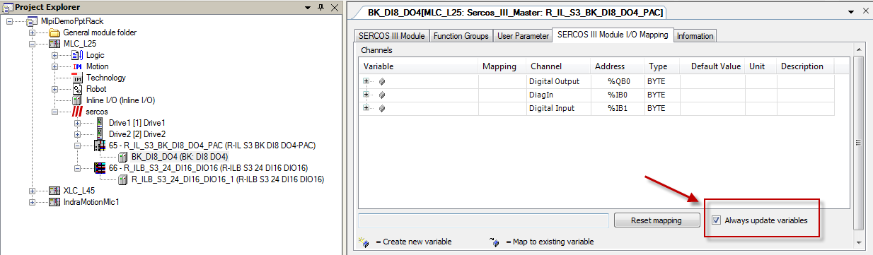
If you want to access data from bus devices through functions of the LogicLib (i.e. mlpiLogicReadMemoryAreaUchar, ...), then the specific I/O devices have to be part of the cyclic I/O data exchange list. By default, only I/O data which is used in the PLC code is added to the I/O data exchange list. All other variables get optimized out. Therefore, if you have an empty PLC program, you can enable I/O data exchange for a given device manually. If the checkbox 'Always update variables' is enabled, then all input data of the selected device are copied to the input area (%I) and all output data are copied from the output area(%Q) of the project.
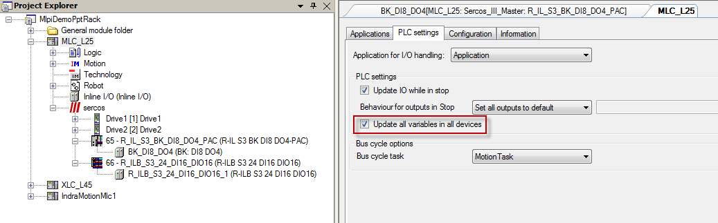
You can enable this option for each device individually as shown above or for the whole project by double-clicking the control and selecting 'Update all variables in all devices' in the register 'PLC settings'.
The functions of the IoLib (i.e. mlpiIoReadFieldbusIoUchar) ignore the PLC input(%I) and output area(%Q) and use direct access to the bus driver. So in order to use the functions of the IoLib for a device, all the update mechanisms of the PLC have to be disabled. Otherwise, the PLC update system and the IoLib functions will overwrite each other, which will result in undefined behavior. So when using the IoLib for a given device, then...
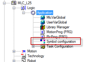
If you want to access PLC variables through functions of the LogicLib (i.e. mlpiLogicGetSymbolsOfApplication, mlpiLogicReadVariableBySymbolUchar), then these functions have to be part of the symbol configuration. You can add variables to the symbol configuration by using the dialog 'symbol configuration' which can be found in the logic configuration of your IndraWorks project.
There is also the option to add a variable or a whole variable list to the symbol configuration by using compiler attributes in your code. This is recommended. Also note, that variables might get optimized out by the compiler if they are not used.
More information on attributes can be found in the IndraWorks help content.
Using the trace could help to find errors on the target device. MLPI functions log different messages to the trace. Often these messages are helpful to solve simple errors or find hints on where to start debugging. These messages can be read using the MLPI. A sample application on how to read from the trace could be found in <install>\mlpi4COM\samples\sample - Using the Trace. For simple debugging purposes, this sample is available as executable application Mlpi Trace Viewer.exe in <install>\mlpi4COM\samples\sample - Using the Trace\bin\Release.
Trace messages are divided in four different types of messages:
Each trace message is sent via a specified module. Trace modules are similar to different channels on which messages can be sent. Only modules which are activated insert messages into a trace buffer. Messages, warnings or errors to modules which are deactivated are discarded.
The following picture shows a screenshot of the Trace Viewer.
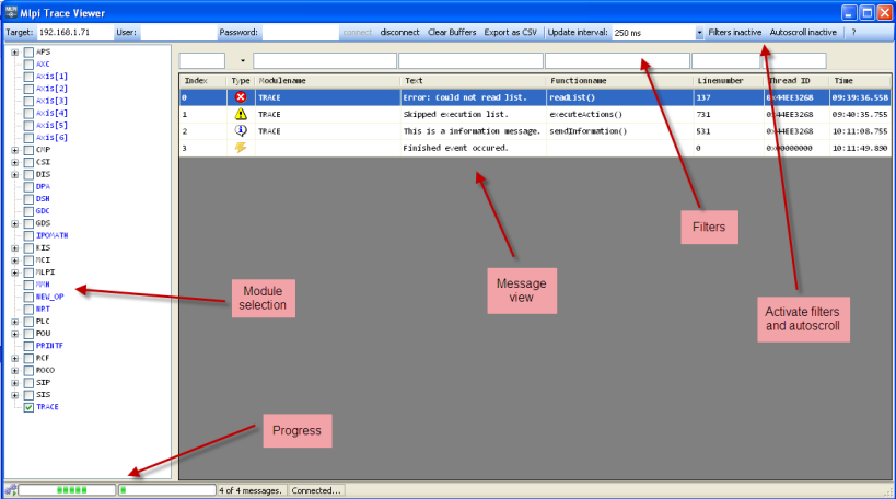
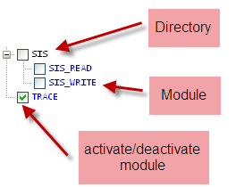
After starting the application, you need to enter the controls ip address and if necessary an username and password. By clicking connect, the available trace modules on the control will be loaded to the module selection tree view. Here, you can activate/deactivate modules by changing the checkbox in front of the module name. A black name identifies a directory node and blue names represent the actual modules.
After connecting to the control, the trace view will populate the message view with available messages. You can order the messages by clicking the column headers. It is also possible to rearrange the columns and change their width. If you want to use the filters above the message view, you have to activate them first by using the button in the menu bar.

